coordinates were 0.9 mm in the X and Z
directions, and 1.9 mm in the Y direction.
Thus, the ground position accuracy was
2.3 mm. In addition, we calculated the
distances between the GCPs with differ-
ent combinations using the coordinates
from the total station measurements and
the photogrammetric triangulation. The
distance differences were used to calcu-
late the mean absolute percentage error
(
MAPE
) that is 1.3 percent. This indicated
that the cameras maintained relatively
stable positions during the slope collapse
period and the
EO
parameters were valid
for all image pairs. Since the eight GCPs
were involved in the bundle adjust-
ment process, this estimated accuracy is
considered as an internal accuracy. The
GCPs were marked targets and their image
coordinates were identified and measured
at a higher accuracy than general surface
features; we can also treat this ground
position error of 2.3 mm as that caused by
the
EO
parameter errors.
The two cameras were synchronized
by a built-in synchronizer, and the nomi-
nal synchronization accuracy was 0.1 ms.
This synchronization error corresponds
to an error of 0.08 mm in the object space
when the maximum average deformation
speed of 0.8 m/s in this experiment was
attained. Thus, the synchronization error
is negligible for this application.
The detected and tracked surface
features were generally non-structured
image features. They were identified
and matched at an estimated accuracy
of 0.25 to 0.5 pixels. Given an image
feature measurement error of 0.25 pixels,
a camera baseline of 1.16 m, and a depth
of 5 m from the baseline to the middle of
the slope, the computed ground posi-
tion accuracy was 0.7 mm in the X and Z
directions and 2.8 mm in the Y direction
(depth), as obtained using a simplified
stereo photogrammetric triangulation
equation (Moffitt and Mikhail, 1980,
Mikhail
et al
., 2001). Hence, the position
error of representative surface features
in the middle of the slope caused by the
image feature measurement errors was 3.0
mm. In a similar manner, we can estimate
that this error ranges from 1.1 mm for the
closest surface features to 5.6 mm for the
farthest features on the slope. Because
the slope surface, and hence the surface
features, changed constantly and were
not accessible during the experiment, no
ground truth was available to verify the
accuracy of these moving surface features.
Overall, the average ground posi-
tion accuracy of the surface features
was approximately
σ
Position
= 3.8 mm, as
estimated using the error propagation
law from the above discussed position
error components caused by errors of the exterior orientation
parameters (2.3 mm), synchronization (0.08 mm), and image
coordinate measurement (3.0 mm) under the assumption that
these errors are independent. This estimated overall position
error is within the range of the external position error of 4.0
mm, which is the RMSE calculated from the differences be-
tween the photogrammetrically triangulated coordinates and
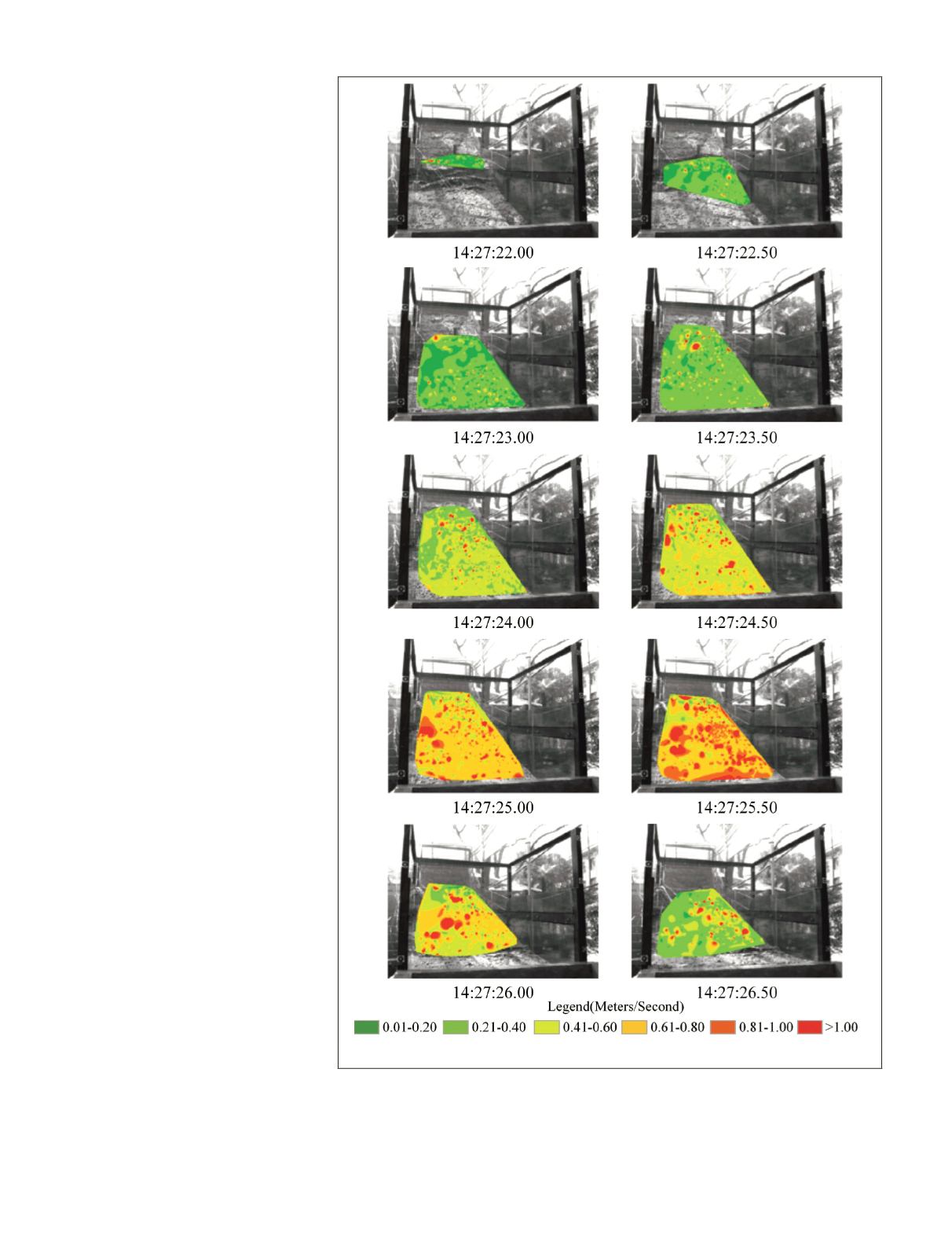
Plate 4. Speed maps with a selected time interval of 0.5 seconds during the slope failure process.
554
July 2016
PHOTOGRAMMETRIC ENGINEERING & REMOTE SENSING


