236
May 2018
PHOTOGRAMMETRIC ENGINEERING & REMOTE SENSING
Common Denominator
for Aerial Survey Cameras
Comparison
There are two groups of aerial survey camer-
as – medium and large format metric camer-
as. There are also two main different types of
mapping areas – urban and rural. There are
three main photogrammetric products that
are often required by the market – orthopho-
to, dense DSM (Digital Surface Model), and
stereo mapping. We shall analyze the usage
of these cameras for different applications.
One of the most popular products for urban
area is a semi-true orthophoto. It features
very narrow orthophoto angle (an effective
angle, which is part of the Field of View
used for orthophoto production and is equiv-
alent to the required small building lean;
see Figures 1 and 2 ) and very high level of
visibility with minimizing hidden, shaded or
obscured areas in the dense urban environ-
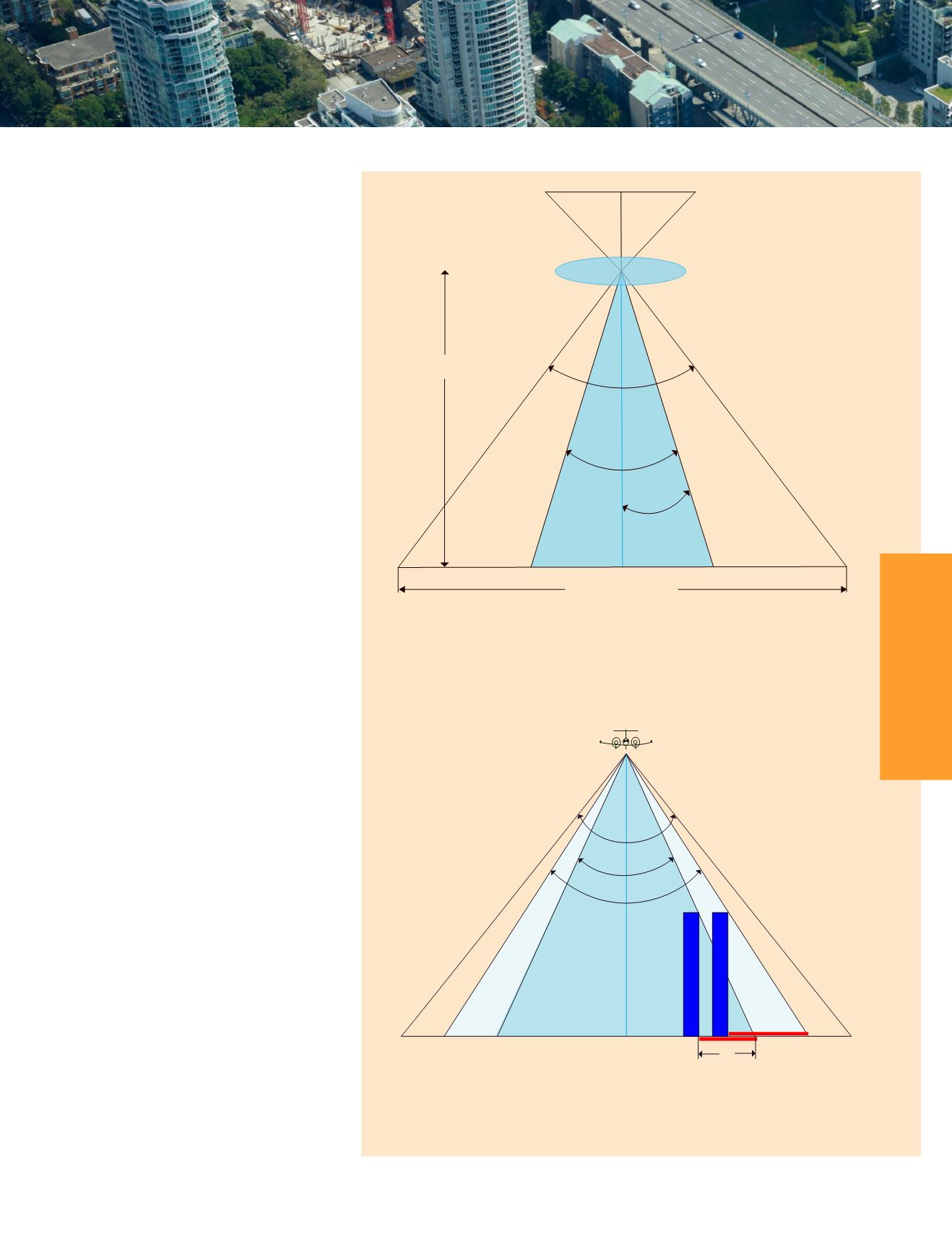
ment (Raizman, 2012). Figure 1 illustrates
the central projection camera, FOV, ortho-
photo angle dedicated for orthophoto area on
the images.
The concept of building lean and its impor-
tance for orthophoto is presented in Figure 2.
Ground resolution (or ground spacing dis-
tance, GSD) of 5 to 15 cm is commonly used
for urban mapping. Orthophoto angles for
orthophoto production in urban environ-
ment lie in the range of 14° to 25°, which
corresponds to 12% to 22% of building lean.
This predefined orthophoto angle (or build-
ing lean), GSD and minimal allowable side
overlap are the three geometric parameters
of aerial survey which enable a geometrically
identical orthophoto (with the same building
lean) from different aerial survey cameras.
These three parameters are considered as
a common denominator for a productivity
comparison of different cameras of different
types.
y
y
F – Focal length;
y
y
H – Flight altitude;
y
y
FOV – Field of View, generally 27° - 110° for different aerial survey cameras;
y
y
2α – orthophoto angle;
y
y
Tg(α) * 100% - Building lean.
Figure 1. Field of View and the Orthophoto Angle.
y
y
2α1, 2α2 – Permissible orthophoto angles;
y
y
L1, L2 – Occlusion
y
y
Tg(α)*100% - Building lean
y
y
If 2α2 > 2α1 then L2 > L1
Figure 2. Field of View, Orthophoto Angle and Building Lean.
H
Full coverage
Orthophoto
FOV
Lens
F
Image plane
2α
α
FOV
2α1
2α2
Orthophoto area
L1
L2


