from the airplane. Due to the remoteness of the crash site and
difficulty involved in safely retrieving the objects, the objec-
tive of this study was to assess the geometry of the purported
airplane components to determine whether additional investi-
gation of these objects, such as retrieval, is merited.
This case study has the following features, which may be
widespread in underwater object analysis. It involved the
search for debris over a wide area in water too deep for div-
ers, so an
ROV
was employed. The
ROV
made an erratic search
pattern as it followed the contours of the steep underwater land-
scape, the slope of a Pacific atoll. As the
ROV
pilot examined po-
tential pieces of debris, there was no scale marker in the video,
and the debris were far enough apart that they never appeared
together in the same frame of the video. Due to the depth, light
from the surface was completely attenuated, and a single light
source originating from the
ROV
was used. Bubbles caused by
cavitation of the propellers also obscured segments of the video.
Digital image mosaicking is a process for combining sev-
eral images by detecting overlapping regions. The detected re-
gions are then used to compute two-dimensional perspective
image transformations, and each image is transformed and
ratioed such that the final mosaic image is from a single per-
spective. Underwater photogrammetry was first used in the
1960s and 1970s using a pair of stereo cameras using adapted
aerial surveying techniques (Hohle, 1971). In the 1980s, im-
age matching to produce a mosaic using a set of local inter-
est points was developed (Moravec, 1977). This method was
subsequently improved into efficient motion tracking and
structure from motion (Harris, 1992). As underwater vehicles
become cheaper and more prevalent, their use has rapidly in-
creased. Underwater photogrammetry is becoming a standard
tool used in many different disciplines, including mainte-
nance and inspection of drilling platforms and oil pipelines,
geological surveys, environmental monitoring, and underwa-
ter archaeology where accurate measurements at short range
is necessary (Leatherdale and Turner, 1991; Gracias
et al
.,
2003; Santos-Victor and Sentieiro, 1994; Maas and Hampel,
2006). Many other underwater discovery methods differ in
accuracy, cost, and simplicity (Telem and Filin 2013; Telem
and Filin 2010). Image-based analysis offers great efficiency
in handling large volumes of detail and the optional benefit
of off-site documentation and analysis (Drap
et al
., 2007).
In addition, underwater photogrammetry can be used for
navigation and orientation in the marine environment where
long range electromagnetic signal communication is absent
(Gracias
et al
., 2003; Gracias and Santos-Victor, 2001).
Image mosaicking technology has many applications. Appli-
cations utilizing panoramic techniques are widely available for
smartphones, where overlapping photographs are taken from
a single position in three-dimensional space. In aerial photo-
grammetry, overlapping photographs are taken from multiple
positions in three-dimensional space, which is heavily used
in scientific and research applications as well. The fieldwork
needed to construct a three-dimensional representation of a site
can be dramatically decreased by using digital photogrammetry.
A single camera can be used to capture photographs to be pro-
cessed off site. The methodology can be seen in the excavation
of the Phanagoria wreck (Zhukovsky
et al
., 2013). At sites where
the use of photogrammetry has been predetermined, a strategy
to overlap photographs in regular patterns can be implemented
(Drap
et al
., 2007; Canciani
et al
., 2003). In instances where pho-
togrammetry was not a priority, additional processing may be
needed to make the footage useful for taking measurements.
Methodology
Overview
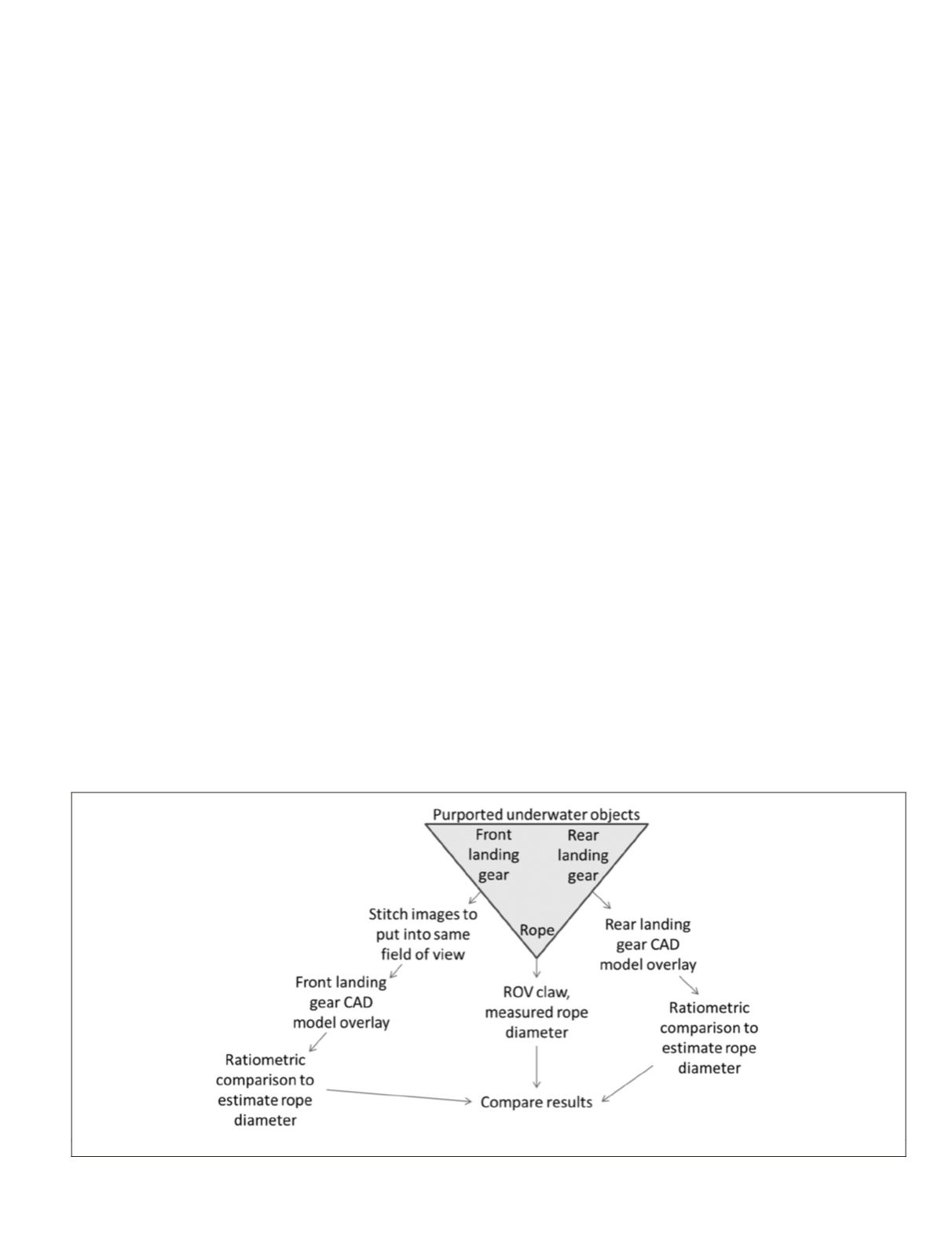
Two purported objects were identified in the
ROV
video, front
landing gear and rear landing gear. A rope was observed
adjacent to both objects. If the size and orientation of each
landing gear could be used to independently measure the
diameter of the rope, then the purported objects are consistent
with the airplane components in geometry and relative size.
Furthermore, the
ROV
claw was also observed holding a piece
of rope, providing a third independent way for measuring the
rope, this time using a known object with known dimensions,
the
ROV
claw. Finally, all three independent measurements of
the rope can be compared to identify whether every mode of
measurement is consistent with each other.
An orthographic reconstruction was attempted, but due to
the quality and path of the video, this was unsuccessful. An
alternative means of measurement using a perspective view
was performed.
Figure 3 illustrates an overview of the approach used for
assessing the geometry of the two suspected objects identified
in the video, the front and rear landing gears. A rope, unam-
biguously man-made, was also identified near each object.
However, the rope was never seen in any frame together with
the proposed front landing gear object. Image stitching was
Figure 3. The overall process used in this case study.
PHOTOGRAMMETRIC ENGINEERING & REMOTE SENSING
March 2016
225


