object-to-camera distance was similarly unknown due to a lack
of any known scale markers in the scene, although a visual es-
timation puts the camera at a height of approximately 3.0 m to
4.5 m. Due to the apparently large distance between the cam-
era and the seabed, the perpendicular perspective, the objects
of interest lying near the center of the perspective view, and a
predominantly flat scene, it was not anticipated that differenc-
es between perspective and orthogonal projections would yield
significantly different results. The validity of this assumption
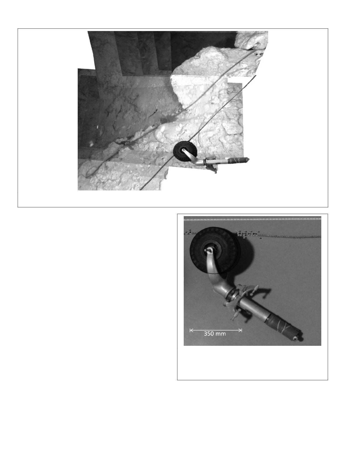
for this specific case was verified by photographing an exem-
plar landing gear from an extant Lockheed Electra Model 10E,
construction number 1042, and a rope with a known diameter,
from the same perspective as in the mosaicked image from the
ROV
video, and comparing measurements from the photograph
with known dimensions of the landing gear and rope. The 15.9
mm diameter known rope was measured to have a diameter of
15.5 mm with a standard deviation of 0.5 mm using this
CAD
model superimposition method, which is sufficiently accurate
for the purpose of this analysis.
The limits of video recording are problematic for many
industries. With only the small field-of-view visible in each
frame of a video, much of the spatial context of each frame
location is lost. Using only a single camera, there are few
options for improvement. Through use of our mosaics, we
were successfully able to observe multiple objects of inter-
est in a common field-of-view. Our method put the selected
images into the same perspective, thus giving unique advan-
tages without physically disturbing the environment. It also
addressed the issue of when a time-stamp or other embedded
watermark obscures objects of interest.
In software engineering, it is increasingly vital to program
using parallel processes to improve performance due to the
increasing core count of modern
CPU
s. Image analysis can be
a highly parallel process, as seen in the
SIFT
algorithm. In our
method, the images were selected in a pairwise manner for
stitching, rather than selected sequentially. Pairwise stitch-
ing requires only requires log
2
(
n
) stitches for
n
-images, while
sequential stitching requires
n
−1 stitches, a marked improve-
ment. Not only is processing time improved, but quality as
well. Error is propagated after each iteration by resampling of
the images after each transformation. In the sequential case
(Figure 7), the first image is stitched
n
−1 times. In the pair-
wise case (Figure 6), the first image is stitched log
2
(
n
) times,
thus drastically reducing propagated error for large datasets.
Figure 13. A photograph of the rear landing gear from the same model aircraft next to a 15.9 mm diameter manila rope is superimposed
over a stitched image, adjacent to the location of the suspected rear landing gear.
Figure 14.The diameter of the 15.9 mm rope was measured at
five locations in the CAD model overlay, using the actual rear
landing gear from a reference aircraft. The rope diameter was
identified using this method to be 15.5 mm with a standard
deviation of 0.5 mm.
230
March 2016
PHOTOGRAMMETRIC ENGINEERING & REMOTE SENSING


