Active FMCW LADAR for
Topographic Ranging
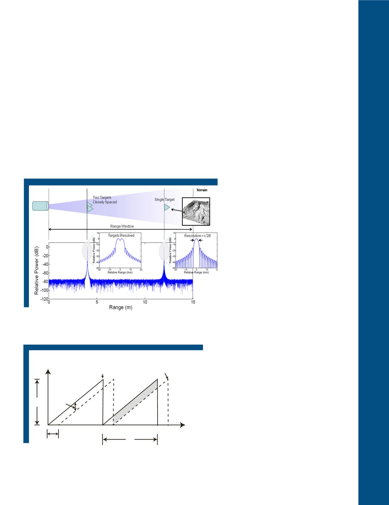
Of active topographic laser scanners, one of the perfor-
mance benchmarks is the range resolution. Range reso-
lution is defined as the distance at which two closely sep-
arated targets being measured simultaneously along the
same ranging vector can be resolved at their
half
power
thresholds. In other words, it is the minimum detectable
spacing limit between two objects along the same ranging
direction measured during the same sampling. Figure 2
depicts a time-of-flight laser scanner and the resolution
of two closely spaced targets. In laser scanning it is de-
sirable to maintain shorter pulses to increase the mea-
surement rate. Furthermore, by shortening the temporal
duration of the pulse, the bandwidth (B) is increased. It
can be shown that the range resolution
ΔR
can be giv-
en as
ΔR=c/2B
where c is the speed of light. Finally, in
order to achieve improved range resolution as described
above, it is advantageous to possess signals with large
optical bandwidths. The conundrum for linear mode,
pulsed LiDAR systems is the trade-off in the maintaining
high peak pulse power (to achieve maximum range) and
decreased pulse duration (to achieve bandwidth for the
highest resolution). Because these measurement features
can be a detriment to system optical components, this lia-
bility hampers scalability. Thus, the inability to scale the
power in linear mode systems limits improving pulsed
systems in both range and signal fidelity.
These limitations are not present in FMCW systems as
the principal setup of an optical FMCW system is the fre-
quency modulated laser which is periodically shifted and
used as a “probing” signal. The periodic, linear frequency
chirped optical waveform (e.g., a sawtooth
bias wave as shown in Figure 3) togeth-
er with coherent detection is collectively
known as FMCW chirped (heterodyne)
LADAR. Figure 1 illustrates this tech-
nique schematically whereby the chirped
laser light is passed through a splitter
where half of the light (TX / RX) is sent
through an optical circulator (to avoid de-
terioration of the laser frequency) before
being sent to the target. The other half
of the light (LO) is the original chirped
signal that is not time-delayed. Light re-
turning from a target is time-delayed as
shown in Figure 3. The range difference
between the target and local oscillator
(reference) is proportional to the inter-
mediate frequency
f
if
(or
κτ
D
in Figure 1).
The recombination of this light produces
a constant frequency offset between the
two chirps, as a result of the time delay,
and appears as a heterodyne of ‘beat note’.
Thus, the target distance is determined
by measuring the beat note frequency
and the range resolution is determined
by the bandwidth of the optical chirp.
Because distance sensing is performed
by electric frequency measurement in
the kilohertz region and the bandwidth
chosen arbitrarily, FMCW LADAR can
determine time delay
(TD
) values in the
picosecond range. In metrological appli-
cations of FMCW this has translated into
micron-level resolution for printed circuit
boards under inspection using automated
FMCW imaging systems (Amann et al.,
2001; Brown, 2011; Reibel et al., 2010;
Kraus et al. 2006).
Figure 2. Range and range resolution determination using a time-of-flight,
linear mode lidar (after Reibel et. al 2010)
Optical
frequency
Reference
signal
Object
signal
Time
t
1
t
2
f
if
τ=2R/c
t
m
f
Figure 3. A schematic of instantaneous optical frequencies versus time
differences between the object target and reference (from Amann et
al. (2001)).
PHOTOGRAMMETRIC ENGINEERING & REMOTE SENSING
November 2017
723


