10
January 2016
PHOTOGRAMMETRIC ENGINEERING & REMOTE SENSING
O
ptical
D
esign
of
the
C
ameras
and
the
G
amma
R
ectifier
There are many methods for rectifying non-linear
distorted imagery. The most widely used requires
matching control points with known locations. A
few use a panoramic model plus image and satellite
motion compensation Sohn (2004). Others, include
local stretch with bi-variate polynomials or similar
functions. These have large errors in areas when there
are multiple sources of non-linear distortion.
Panorama, Earth Curvature, Camera Tilt and Image/
Satellite motion compensation using the camera
optical model require no control points for correction.
Further treatment uses conventional stereo methods.
A few control points are needed for georeferencing.
Georeferencing must be repeated in different parts
of a strip since the USGS manually determined
strip corners from ephemeris latitude/longitudes
(Sealander, 1996) are imprecise (1/3 arc-second).
Additionally, there is a latitude error due to the use of
the Hough ellipsoid instead of WGS84/GRS80.
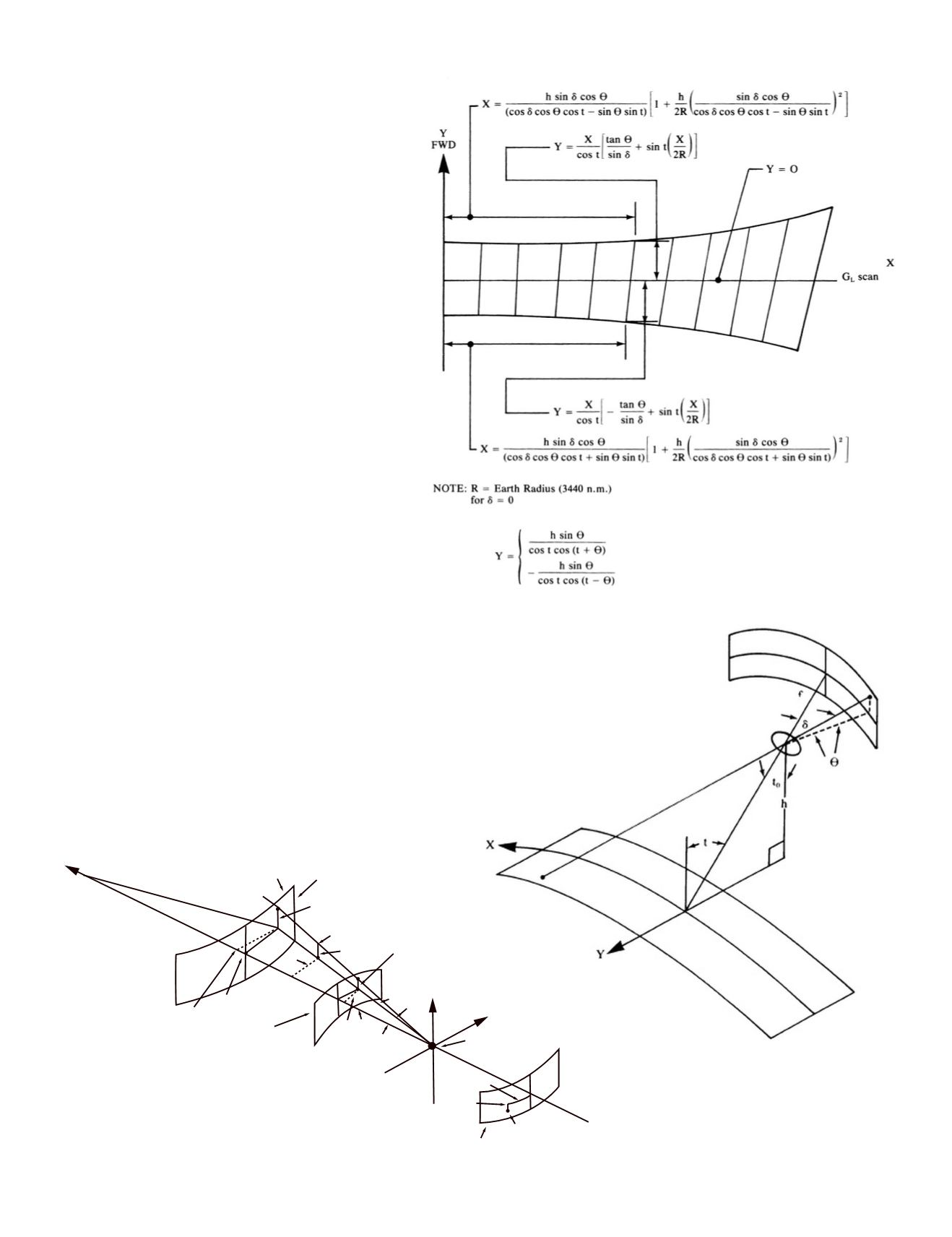
Section 5 of the Gamma Rectifier Report (Figure 7)
contains a mathematical model derived from the
known properties of the optics, the satellite height and
Earth curvature. The Ondrejka “footprint” (Ondrejka,
1980) in Figure 8 shows the effect of the three principal
distortions when a gridded rectangle at the curved film plane
in the satellite camera, scanned through a slit as the camera
moved, is projected on to a curved model of the Earth with the
tilt of a forward or aft pointing camera.
For software emulation, the Aschenbrenner - Ondrejka
equations must be inverted so that a nominal rectangle is on
theEarth’s surface and distortion is at the filmcylinder surface
so that grayscale values can be estimated by interpolation
for X-Y ground coordinates on a fictive flattened cylindrical
Easel in nontilted positon
Z
r
r
V
z’
x’
P’
∆
Z
2
Y
1
= Y
2
P’
y’
P
y
1
= y
2
x
1
x
2
z
1
F
Y
α
X
x
1
y
1
P
Positive postion
image (to be
rectified)
Center of projection
Image (to be rectified)
Negative
postion
Figure 7. Gamma Rectifier geometry.
The easel with output film models Earth
curvature.
Figure 8. The Ondrejka
Footprint (Ondrejka 1980
Figure 17-47a). above and
notation on the right.


