PHOTOGRAMMETRIC ENGINEERING & REMOTE SENSING
January 2016
11
Earth. Errors are negligible with this cylinder approximation
instead of an ellipsoid at the satellite heights involved.
Hilbert (Hilbert 2005) designed the optics of the ITEK
Gamma Rectifiers. From 1963 to 1975, Hilbert held many
management positions at ITEK: he was the director of optics,
the manager of the optical engineering department, the chief
optical engineer, and the supervisor of optical design. He was
responsible for all engineering and manufacturing necessary
to design and produce the mounted optics, opto-mechanical
design, optical fabrication, assembly and testing. He wrote
the only previously published account for the Gamma
Rectifier although, without referring to the details in the
classified Report.
A
rmy
M
ap
S
ervice
I
nstallation
One of the 12 rectifiers was at the US Army Map Service
installation. Clifford J. Mugnier, now of Louisiana State
University, was Engineer Officer there from 1968 to 1973
(Mugnier 1973). He collected all the AMS photos used here,
Figures 9 to 12. The Gamma Rectifier made intermediate
distortion-corrected projection prints from the 70 mm film
negatives to 9 inch transparency film from the forward and
aft looking cameras with Panoramic, Earth Curvature and
Tilt correction. Frame images from an auxiliary modified
Hasselblad camera for orientation as described by Madden
(1996, pp. 42-48) were processed with an OMI Nistri TA-3P
plotter, Figure 9.
Mugnier writes “The stereo compilation was indeed done
from the pan imagery, but all of it was controlled by the
Figure 9. OMI-Nistri TA-3P at AMS.
frame camera imagery. Each frame image usually had
several hundred ‘pass points’ marked in stereo and computed
with classical aero-triangulation software in order to provide
sufficient control for the orientation of the pan imagery for
stereo compilation.
Earlier, some transparency pairs from the Rectifier were
processed with a classified Kelsh M4 plotter and later with
UNAMACE stereo plotters for mapping at 1:250,000 and
1:50,000.
Each pass point was triangulated with a frame camera-
only solution of thousands of points computed for control
of the stereo pan, and each control point computed with
the aero-triangulation software was also marked in stereo
(with differential zoom Wild PUGs and differential zoom
MicroMarks Figure 11) onto the pan imagery. The pan
imagery was not computed with the KH-4B system; it was
included into some computations when the analytical plotters
were developed with computer-controlled dove prisms, but
that was for the KH-9 “Big Bird” pan imagery.
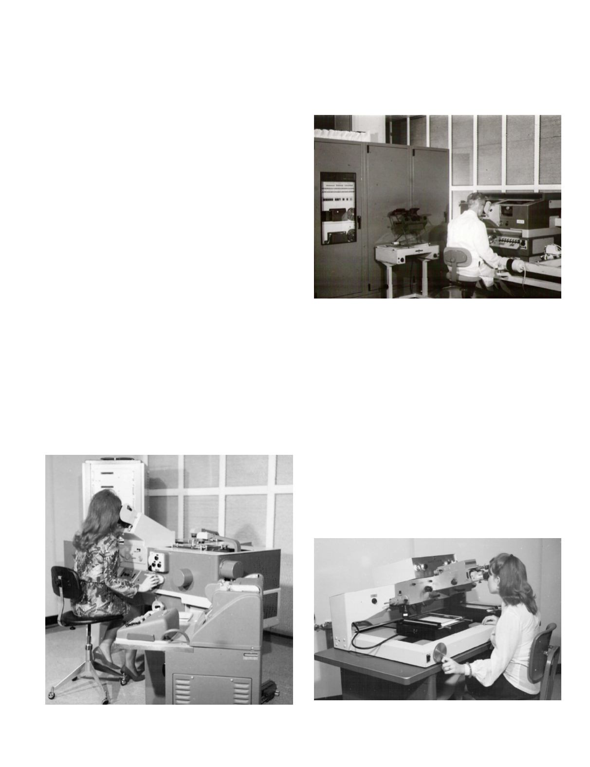
Figure 10. An OMI-Nistri AS-11a analytical stereo plotter was used
for line, symbol mapping and contouring of KH-4B images at
AMS.
Figure 11. MicroMarks stereo pass point marker.


