The changes of interest in this study are any sort of altera-
tions in the status of urban objects that cause variations in the
spectral values registered by imaging sensors such as a new
building/road construction or renovation of a building roof.
PWCR-Based Change Detection Framework
In this study, a framework is proposed for
PWCR
-based change
detection which is composed of three major components:
preprocessing, patch-wise coregistration (
PWCR
), and change
analysis. Figure 1 depicts an overview of the presented frame-
work for change detection. The three components will be
explained in detail in this section.
Preprocessing
The preprocessing component of this study is composed
of image fusion and segmentation. Fusion of multispectral
images with the pan image of the same temporal dataset is
performed in order to produce multispectral datasets with
higher spatial resolutions. FuzeGo software, formally UNB-
pansharp, is used for this purpose (Zhang, 2004). The next
step in preprocessing is image segmentation.
As shown in Figure 1, the base image is segmented. There
are different methods for image segmentation in the literature
such as multi-resolution segmentation and fuzzy c-means
(Dey
et al.
, 2010). However, selection of a method which
produces segment borders precisely fitting object borders is a
challenging task (Tong
et al.
, 2012). The more precise object
borders generated in the segmentation step, the better change
detection results can be expected.
Here, in order to avoid false change detection results due
to the occlusion and the relief displacement effects, each seg-
ment must contain either a horizontal (e.g., building roof) or a
vertical (building façade) part of an object. For example, a seg-
ment can contain a part of a building roof or a part of build-
ing façade, but not both of them. This sorting of segments are
referred to as
patches
in this study.
To achieve this level of segmentation, we first over-seg-
mented the base image using the multi-resolution segmenta-
tion method. Then, a fuzzy-based segmentation parameter
optimization tool (FbSP tool) developed by Tong
et al.
(2012)
is employed. This tool provides optimized scale, shape, and
compactness parameters to merge the segments generated in
the first place and produce optimized segmentation results.
In the output of the segmentation step, each pixel in the
base image will have a code specifying its unique patch
ID
denoted by
S
k
, 1<
k
<
K
, where
K
is the total number of patches
in the image.
Patch-Wise Coregistration
In this coregistration method, we first find the position of
the corresponding points in two images and then from the
corresponding points we generate the corresponding patches.
This process is done in three steps which are explained in
this section.
Step 1: Image-Ground Coordinate Look-Up-Table Generation
To find the corresponding image points every
DSM
pixel is
back-projected to the both image spaces using the associated
RPCs
. The footprints of projection of each
DSM
pixel in the
images reveal the position of the corresponding points in the
image spaces provided that
RPCs
are error free.
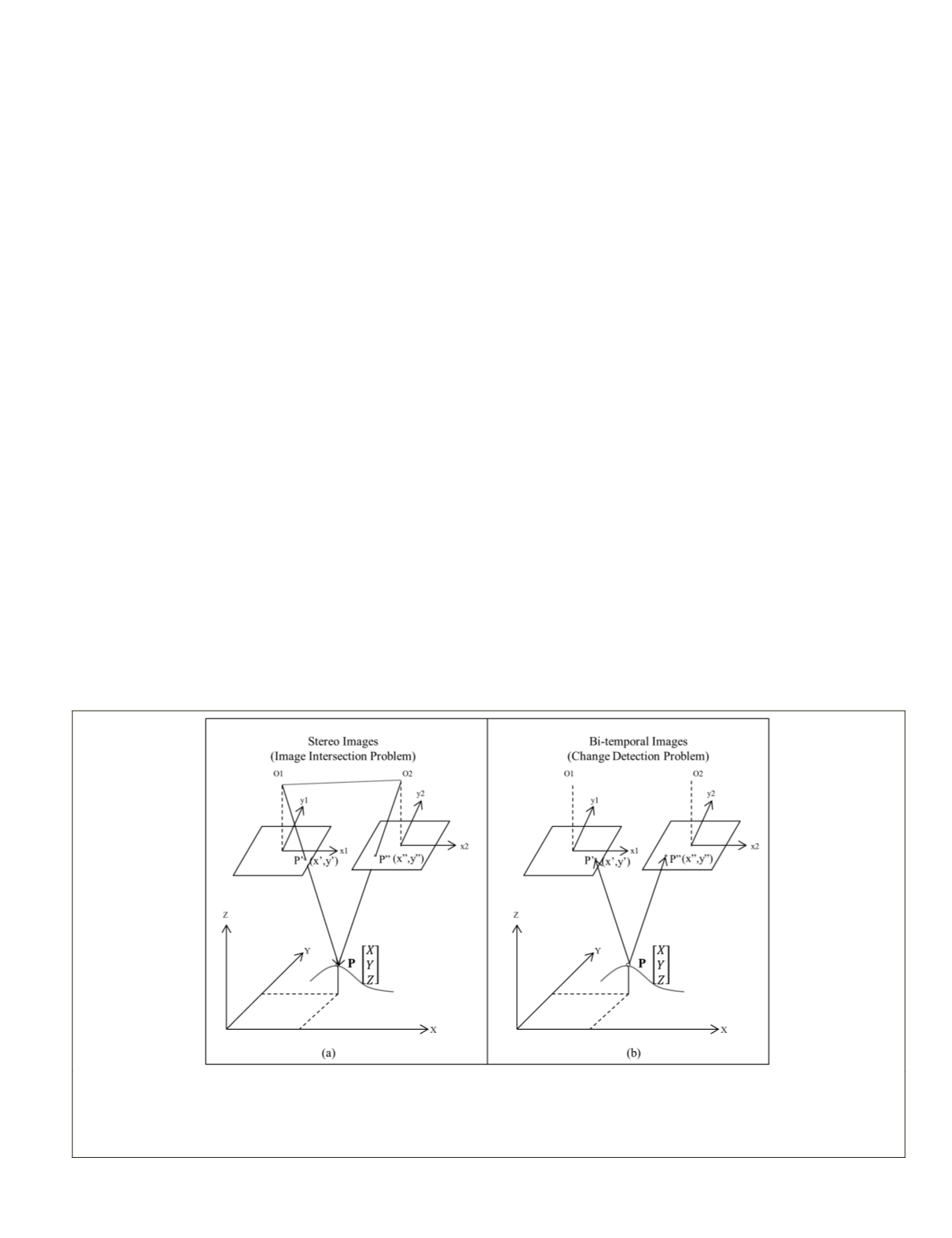
In fact, this step is based on the inverse of the space inter-
section problem in photogrammetry. In space intersection,
first, the same area is imaged from multiple view angles. Later
on, the image coordinates of the matching image points along
with the exterior orientation parameters (related to sensor
position and attitude) of each image are used to calculate
the object coordinates of the ground points (Figure 2a). In
the image intersection problem, the image coordinates of the
matching image points (
x
1
,
y
1
), (
x
2
,
y
2
) along with the exterior
orientation parameters are known and the ground coordinates
(
X, Y, Z
) are unknown.
However, in the presented coregistration method it is as-
sumed that the ground coordinates (
X, Y, Z
), given by
DSM
,
along with the exterior orientation parameters, given by
RPCs
in satellite images, are known and the coordinates of the
matching image points ((
x
1
,
y
1
), (
x
2
,
y
2
)) are unknown.
Nevertheless, because of time difference between the
images, it is not certain if the matching points/objects still
exist. Thus, using the reverse space intersection, which is the
Figure 2. Comparison between the space intersection method and the proposed coregistration method: (a) In space intersection, the
interior and exterior orientation parameters along with image coordinates of matching points (P′ and P′′) are used to calculate the ground
coordinates (X,Y,Z) of ground point P; and (b) The basic idea of the proposed coregistration task is to use the 3D coordinate of the ground
point P(X,Y,Z), obtained from DSM, along with the exterior orientation parameters, obtained from image RPCs, for finding the correspond-
ing points in the bi-temporal images (P′ and P′′).
PHOTOGRAMMETRIC ENGINEERING & REMOTE SENSING
July 2016
523


