PHOTOGRAMMETRIC ENGINEERING & REMOTE SENSING
June 2014
485
crop species of interest (Figure 2). In comparison
with today’s technology, this approach undoubt-
edly sounds like something out of the stone age!
Although this method of analyzing the data was
rather crude, the results did indicate that multi-
spectral data had a great deal of potential. How-
ever, it was clear that before we tried to identify
agricultural disease or insect infestations, we
needed to determine if we could simply identify
different crop species using such multispectral
data. These initial efforts also indicated the im-
portance of obtaining remote sensor data at the
critical stages of crop development. Some crops
could be differentiated at certain times during
the growing season, but not at other times. Of the
five sets of data obtained that summer, the ability
to differentiate the various crop types was best
in the data obtained on June 25, so that was the
data set that was analyzed in most detail.
It is interesting to note that because the scan-
ner imagery was classified as “confidential”, I could not include
illustrations of the imagery in any publications or even show
it to other people who did not have proper clearance. (It was
not until 1967 that the scanner system was declassified and
imagery obtained from it could be shown to the general public
and used in publications.) Because of this limitation for display-
ing any of the scanner imagery publically, I developed “artist’s
concept” drawings of the gray tones of the various agricultural
fields for the different wavelength bands which visually approx-
imated the relative differences in reflectance or emittance (Fig-
ure 3). Sometimes I found some interesting and puzzling fea-
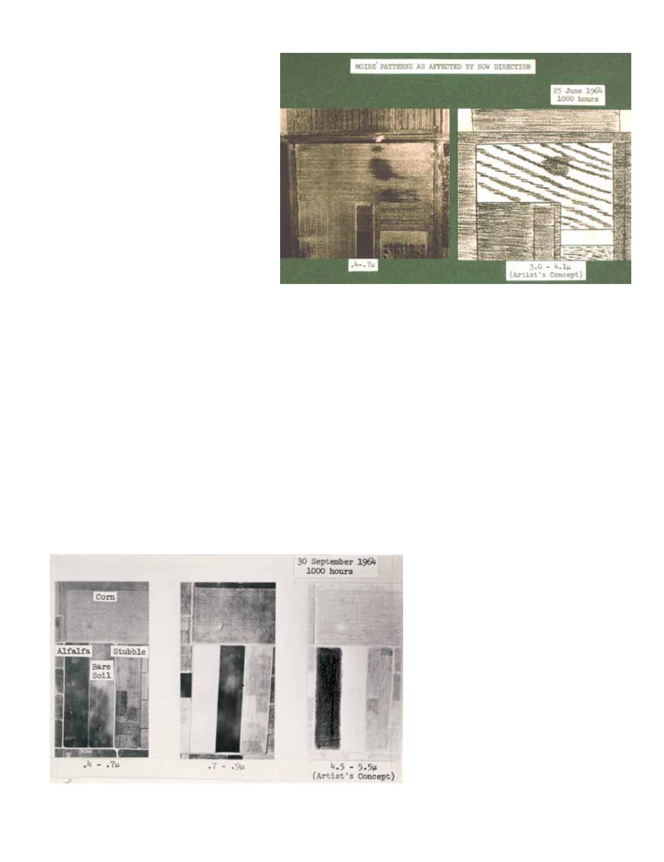
tures in the imagery. Scanner data obtained on June 25, 1964
displayed moiré patterns in a number of fields of row crops,
especially corn fields (Figure 4). It was determined that these
patterns would occur if the scan line was at a slight angle to the
row direction, and if the flying height of the scanner was such
that the scanner ground resolution was similar to the distance
between the rows of the crop. Unless both of these conditions
were met, there would be no moiré patterns on the imagery.
These early, rather crude attempts to manually interpret 18
wavelength bands of black and white imagery led to the conclu-
sion that methods needed to be developed to quantify the analy-
sis processes. One approach that was considered involved use of
a densitometer to measure the photographic opacity of the film
for each agricultural field of interest in each wavelength band
of data. This technique would provide a quantitative set of data
for analysis. However, before this approach was implemented
to any large extent, the University of Michigan engineers had
developed a new system of multispectral scanners. The scan-
ners and associated cameras were then flown in a DC-3 aircraft
(Figures 5 and 6). This new scanner system consisted of four
scanners, obtaining data in a total of 18 wavelength bands. The
primary scanner obtained data simultaneously
in 12 bands (10 visible and two near infrared),
and these data were recorded on analog tape.
The analog data could be changed later into dig-
ital data through an analog to digital converter.
In addition to the 12-band multispectral scanner,
the University of Michigan system also collected
a single band in the U.V. (0.32 - 0.38 µm) por-
tion of the spectrum, four bands in the middle
reflective IR and shorter wavelength thermal IR
region (1.5 - 5.5µm), and one band in the longer
thermal IR (8 - 14µm) portion of the spectrum. It
was this scanner system that provided the data
for the research needed to effectively develop and
test digital pattern recognition techniques. Some
of the analysis methods and pattern recognition
techniques developed in these early years of re-
search are still in use today, although often as
modified versions of the original.
Figure 3. Multispectral response of corn, alfalfa, stubble, and bare soil, illustrating the “artist’s
concept” drawing of the classified scanner imagery (from: Hoffer, 1967).
Figure 4. Moiré patterns in row crops (corn in this case), caused by the correct combi-
nation of row direction and scanner ground resolution (from: Hoffer, 1967).


