the next Section for the performance of detecting buildings
based on the generated disparity.
Registration-based Technique for Mapping Aboveground Disparities (RMAD)
The key concept for the proposed technique is to process the
original
VHR
stereo images in a way that allows image match-
ing techniques to measure the disparity of aboveground objects
only. This process includes four steps: (1) minimizing the relief
distortion caused by the terrain in the stereo images, (2) remov-
ing the y-disparity between the stereo images, (3) co-registering
terrain-level features and, hence, eliminating their x-disparity,
and (4) mapping the disparity of the remaining x-disparity
values that correspond to off-terrain objects. These steps are
further discussed and justified in the following subsections.
Minimizing Terrain Relief Displacement
The variation in the terrain elevation produces relief distor-
tions in any acquired image. Because of the different viewing
angles for a stereo pair of satellite images, these distortions
make the relative distance between any two points vary from
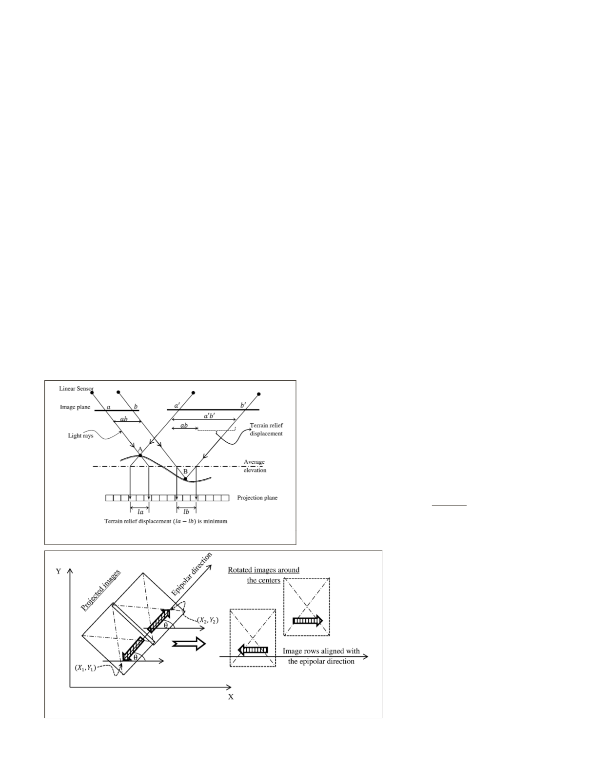
one image to another. Figure 1 describes this effect by show-
ing the difference in the distance between two points in the
two image planes. It is clear that a straightforward co-registra-
tion of the terrain-level features in a stereo pair is impossible.
Typically, relief distortion can be completely corrected for if a
terrain model of the imaged area is available. However, since
such models are not always available, minimization of this
distortion should be considered instead.
Dense urban areas are characterized by reasonable road
grades based on engineering design standards. For instance,
the standards of the American Association of State Highway
Transportation Officials (
AASHTO
) limit the maximum grades
of urban areas at 50 km/h design speed to the range of 7 to
12 percent depending on the terrain and road class (
AASHTO
,
2001). The resulting relief effects from such road grades can
be corrected by re-projecting the images onto a common
object-space plane that minimizes the relief displacements.
Such a plane is defined by the average elevation of the terrain
variation, as demonstrated graphically in Figure 1.
The image re-projection process can be executed by (a)
finding the approximate ground coverage of the stereo images
from their meta-data, (b) constructing a 2D grid with a spacing
distance similar to the ground resolution of the images, and (c)
projecting the stereo images to the plane of the average terrain
elevation using the relevant sensor model information. We
strongly recommend that the resampling process of this step
is to be done in the image space for better visual quality of the
output images. This is achievable through the use of ground-
to-image (forward) rational function model (
RFM
), which is the
most popular generalized sensor model (Tao and Hu, 2001).
Eliminating Y-disparity of the Stereo-pair
Eliminating the y-disparity between the stereo images makes
all conjugate points in the left image lie on the same line in the
right image. This situation is realized by rectifying the stereo
images into the epipolar geometry. Linear array sensors used
in all
VHR
satellite systems acquire scenes with a different per-
spective center for each image column. This effect destroys the
straightness of the epipolar lines as comprehensively discussed
by Habib
et al.
(2005). However, it is concluded by Wang
et al.
(2011) that the epipolar curves of satellite stereo images can be
approximated by straight lines if the images are projected onto
a common projection reference plane (
PRP
) in the object space
(
PRP
epipolarity model). Thus, to maintain the terrain relief dis-
tortion at minimum, the common projection plane in the object
space must be at the average terrain elevation of the imaged
area. Consequently, our study adopts the average terrain level
for the
PRP
epipolarity model to eliminate the y-disparity of the
stereo-pair and to minimize the terrain relief distortions.
Following this step of image projection, the stereo images
need to be relatively reoriented along the epipolar direction
to make the corresponding points lie on the same image row.
This epipolar direction should be identified before applying
the relative orientation. A practical approach to calculate the
epipolar direction is to match a set of distinct points on the
tops of high buildings in one projected image to their conju-
gates in the other image. The object-space
PRP
locations of any
of these points can be used directly to calculate the epipolar
direction in the object-space
PRP
plane as in Equation 1:
θ
=
−
−
−
tan
1
2
1
2
1
Y Y
X X
(1)
where (
X
1
,
Y
1
) and (
X
2
,
Y
2
) are the object-space
PRP
coordi-
nates of the point in the two projected
stereo images. A rotation by the amount
of angle
θ
can then be applied to the two
projected images around their centers to
make their rows parallel to the epipolar
direction.
A vertical shift transformation should
also be applied to align the coordinate
systems for both images. This shift can be
calculated using the coordinates of one
point pair in both of the oriented images.
The whole process is described in Figure
2 which illustrates the applied rotation
around image centers. The product of
this step is an epipolar stereo pair with
approximated straight epipolar lines, and
all conjugate points lie on the same row
in both images.
Figure 2. Image reorientation to make the image rows parallel to the epipolar direction.
Figure 1. Minimization of terrain relief displacement.
PHOTOGRAMMETRIC ENGINEERING & REMOTE SENSING
July 2016
537


