correspondence, the initial camera parameters are refined in
the proposed novel
LR-RANSAC
verification framework using
randomly selected matched line pairs for the generation of the
camera parameters hypothesis.
LR-RANSAC
builds upon the concept of Randomized
RANSAC
(
R-RANSAC
) (Chum and Matas, 2002). The premise of the
original
R-RANSAC
algorithm was to avoid proceeding to the
computationally demanding hypothesis-verification stage
when randomly sampled feature correspondence sets are
outlier prone. This was done by assessing the quality of the
sample set using a so-called “pre-verification” test. In this
work, we propose (a) a modified pre-verification test and an
alternative test to address our line-based matching problem,
and (b) we introduce an evidence-based verification approach
to optimally select a “winning” camera parameter hypothesis
using prior knowledge from stored
CAD
models. The
LR-
RANSAC
stage (dashed lines in Figure 2) is an iterative process,
in which the random sampling of line pairs is triggered when
the pre-verification test has failed or the full-verification mea-
sure is finished. This process continues until the
LR-RANSAC
iterations reaches to its pre-set maximum number. The next
four sections describe in detail the components of the initial-
ization and the
LR-RANSAC
stages.
Initial Estimation of Camera Parameters
Our method uses vanishing point (
VP
) geometry of the image
frames to establish an initial approximation of the camera’s
rotation angles and its focal length. We assumed that our
images of interest (e.g., indoor hallways and outdoor urban
street scenes) contain predominantly parallel lines in three
orthogonal directions, which converge towards
VP
s in the
2
D
image space. This is referred to as the Legoland World
assumption (Coelho
et al
., 1990). Straight lines are extracted
using the Canny edge detection method (Canny, 1986) as
modified by Kovesi (Kovesi, 2011). Perceptual grouping rela-
tions, particularly parallelism and proximity, were used to
merge the extracted line segments. Our merging procedure
assumes that if two image lines are parallel (i.e., similarly
oriented), their proximity is a reasonable cue for considering
them as candidates for merging. Two parallel lines are con-
sidered proximate if there is at least one pixel-to-pixel spatial
distance between the two lines that is less than a user-set
distance threshold
T
(
T
= 5 pixels was set for all our experi-
ments). Two lines are merged into a single image line using
least squares fitting if the proximate condition is met. This
procedure is conducted recursively for all parallel lines in
the image until no more proximate line candidates exist. For
the determination of the vanishing points and the classifica-
tion of the extracted image lines into X, Y, and Z directions,
respectively, we adopted Rother’s approach (Rother, 2002).
It provides reasonably accurate estimations of the
VP
while
maintaining minimal computational effort in comparison to
alternative
VP
detection approaches. The fundamental idea of
classifying the image lines into the X, Y, and Z directions is
based on scoring the support of vanishing point candidates
for the image lines which converge to them (Persad, 2012).
The location of the vertical vanishing point
VP
Y
must first be
determined along the vertical-Y axis direction in the image
coordinate system. Lines that support the
VP
Y
point are classi-
fied as Y-direction lines. Then the horizon line on the image
plane on which the
VP
X
and
VP
Z
are located is determined.
Lines intersecting with the horizon line support either
VP
X
or
VP
Z
. We distinguish
VP
X
from
VP
Z
based on the right hand
orthogonal system. Therefore, the lines intersecting the
VP
X
are classified as X-direction lines and lines intersecting the
VP
Z
are classified as Z-direction line.
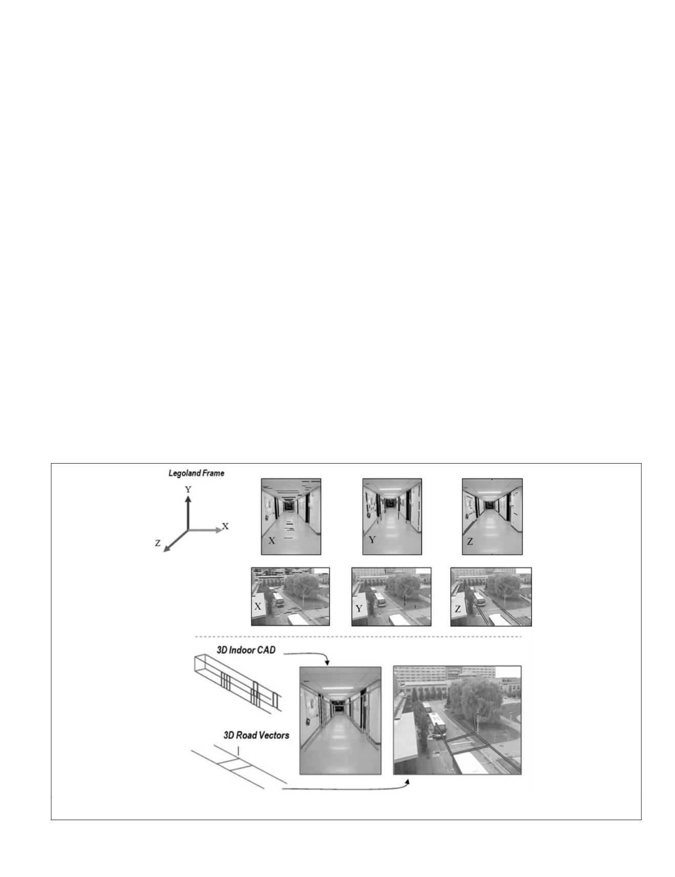
Figure 3 (top row) shows sample results of lines classified
in corresponding Legoland World directions. Given the
VP
directions (the directions from the camera perspective center
to the
VP
s), the initial
VP
-based camera parameters were deter-
mined according to the principles of perspective geometry as
Figure 3. Top row: Image lines classified according to the dominant Legoland World directions (left) for an indoor (top) and outdoor scene
(below). Bottom row: Back-projection of 3D Wireframes to images with sub-optimal fitting using the initial camera parameters.
PHOTOGRAMMETRIC ENGINEERING & REMOTE SENSING
November 2015
849


