to be minimized for estimation of the four camera parameters
of the hypothesis.
For the line pair in Figure 5, the perpendicular distance of
an endpoint from the projected wireframe model line
L
M
to
the extracted image line
L
I
is represented as the distance func-
tion
(Luhmann
et al
., 2006) as follows:
d
v v u f
U
Q
u u v f
W
Q
u
q
j
j
pp
j
j
pp
j
1
1
2
1
2
1
.
.
=
−
(
)
−
+ − +
(
)
−
+
v u v
u u v v
j
j
j
j
j
j
j
2
2 1
1
2
2
1
2
2
−
(
)
−
(
)
+ −
(
)
(1)
where
u f
U
Q
u and v f
W
Q
v
pp
i
pp
i
−
=
−
=
1
1
and
u,v
= 2
D
image coordinates; where
i
and
j
refers to the
endpoints of the line pair,
L
M
and
L
I
,
respectively;
u
pp
,v
pp
=
coordinates of the camera principal point;
f
= camera focal
length;
U = r
11
(X-X
0
) + r
12
(Y-Y
0
) + r
13
(Z-Z
0
)
;
W = r
21
(X-X
0
) +
r
22
(Y-Y
0
) + r
23
(Z-Z
0
)
;
Q = r
31
(X-X
0
) + r
32
(Y-Y
0
) + r
33
(Z-Z
0
)
;
r
mn
= orthogonal rotation matrix elements as functions of ω (tilt), φ
(pan) and κ (roll) angles between camera and wireframe model
coordinate systems where
m
= 1,2,3 and
n
= 1,2,3;
X,Y,Z
= 3
D
wireframe model coordinates; and
X
0
,Y
0
,Z
0
= World coordi-
nates of camera lens’ perspective center
The initial coordinates of the projected wireframe model
line (
u
1
i
,
v
1
i
) and (
u
2
i
,
v
2
i
) are determined based on the initial
camera parameters and are to be corrected as functions of
the yet to be determined final camera parameters. Equation 1
expresses the relation between 3
D
wireframe model space and
2
D
image space. The distances
d
qn
between each of the four
line pairs
are functions of the unknown final camera param-
eters and are to be minimized through a least squares optimi-
zation process. We obtain a solution to this over-determined
system of distance equations (eight
d
qn
equations with four
unknown camera parameters) by applying a parametric non-
linear least squares adjustment (Wells and Krakiwsky, 1971).
The optimization process aligns the wireframe and image
linear segments while simultaneously providing corrections
to the initial camera parameters and eventually resulting in
an estimation of the final ones. This final solution forms the
hypothesis for the estimated camera parameters and must
be verified before acceptance. The acceptance process of the
camera parameters hypothesis is performed in two stages as
described in the following Sections.
Pre-verification Test
The pre-verification test provides a quick measure of the
quality of the hypothesized camera parameters and serves as a
precursor to the full verification step. Limited computational
demands and the ability to not discard feasible hypotheses
are the key characteristics for designing our pre-verification
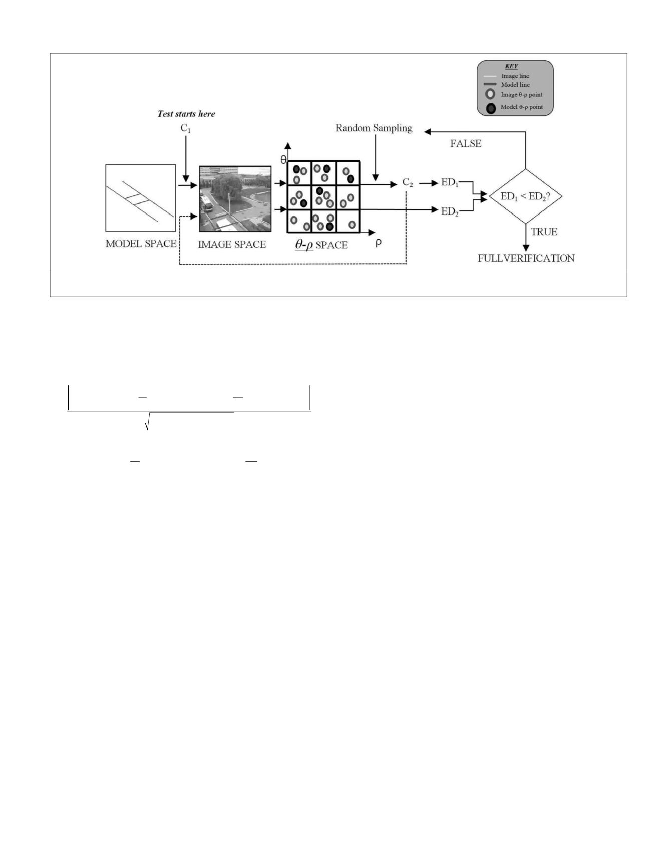
test. Figure 6 illustrates the overall workflow of the pre-verifi-
cation test.
The initial camera parameters set, C
1
estimated from
VP
analysis previously described is used to back-project the
wireframe lines on the image. C
1
is fixed during the entire
pre-verification process. These back-projected wireframe
lines on the image, along with all the image lines (potential
matching lines) are then transformed into
θ
-
ρ
space (Figure 6).
Then, a set of four wireframe-to-image line pairs are randomly
selected from
θ-ρ
space and their Euclidean distances (
ED
1
)
between the four pairs of points are calculated. These ran-
domly selected line pairs allow us to compute a new camera
parameter set C
2
using the approach in the previous Section.
Using C
2
, the randomly selected wireframe lines are then re-
backprojected into the image and then into the
θ-ρ
space once
again and their Euclidean distances (
ED
2
) distances between
the new four pairs of points are calculated. Smaller Euclidean
distances (
ED
) in
θ-ρ
space between the four wireframe and
image feature point pairs suggests that there is a closer wire-
frame-to-image alignment than the one that can be achieved
by the
VP
-based initial camera parameters C
1
and the camera
parameter hypothesis C
2
is considered to be a possible solu-
tion. Otherwise, the C
2
parameters are discarded. Then four
new line pairs are randomly generated once again followed by
computing a new hypothesis of camera parameters using the
least squares solution of the previous Section. This iteration
continues until all the hypotheses are generated from entire
matching samples and the dimension is determined through
RANSAC
principle (Hartley and Zisserman, 2003).
Evidence-Based Hypothesis Verification
The key role of pre-verification test is limited to the reduction
of the size of hypothetical camera parameter space through a
quick measure of co-registration quality, but it is not a global
parameter solution that maximizes the wireframe-to-image
correspondences. Following successful pre-verification, a
full-verification of the hypothesis is performed to optimally
determine a winning solution of the unknown camera param-
eters. This full-verification is performed by re-back-projecting
the entire 3
D
wireframe model lines into the image using our
Figure 6. Illustration of pre-verification workflow where the hypothetical camera parameter set C
2
is pre-tested before the full verification
starts (C: camera parameter set; ED: Euclidean distance).
PHOTOGRAMMETRIC ENGINEERING & REMOTE SENSING
November 2015
851


